












1. Introduction to 3D Vision Dimensional Metrology
1.1 What Is 3D Vision Dimensional Metrology? Core Principles
3D vision dimensional metrology is a cutting-edge industrial quality control technology that enables precise three-dimensional measurement of complex free-formed surfaces using optical imaging. Unlike traditional contact tools, it leverages three key methods to capture detailed 3D data:
Structured light scanning: Projects predefined light patterns (e.g., grids, stripes) onto objects; industrial cameras capture distorted patterns, and triangulation algorithms calculate depth to generate 3D point clouds.
Laser triangulation: Emits a laser line or dot array; cameras track the laser’s position on the object surface, using trigonometry to compute depth—ideal for high-precision measurements (e.g., PCB solder joints, thread profiles).
Binocular stereo vision: Mimics human eyes with two cameras; compares disparities between images to reconstruct 3D coordinates, suitable for large-scale objects like automotive body panels.
The foundational principle across all methods involves projecting active light sources (blue LED, laser) and calculating the time difference or positional shift between emitted and reflected light to obtain depth information. This allows simultaneous capture of X, Y, and Z coordinates for every point on the object, enabling accurate scene modeling, defect detection, and robotic part positioning—critical for modern manufacturing efficiency.
For example, structured light 3D scanners use a projector and camera set at a fixed baseline. By comparing the angle and position of projected patterns in captured images, they create dense 3D point clouds of the object surface. Stereo cameras enhance accuracy further, making this method a top choice for medical device inspection (e.g., 10 mm-diameter gears with ±5 μm tolerance).
1.2 Technical Architecture of 3D Vision Metrology Systems
A high-performance 3D vision dimensional metrology system combines hardware and software to deliver precise, reliable measurements. Here’s a breakdown of key components:
Hardware Components
Component Function Example Specifications
Industrial Cameras/Lenses Capture surface images; resolve fine details 4-megapixel monochrome CMOS sensors; double-telecentric lenses (for wide-area measurement)
Illumination Modules Provide high-contrast lighting; avoid ambient light interference Blue LED (eye-safe, no laser compliance needed); laser line generators (for triangulation)
Motion Platforms Enable systematic scanning of large/complex objects X/Y/Z axis stages with ±0.1 μm repeatability
Scanning Modules Capture 3D data via optical principles Time-of-Flight (ToF) scanners (10,000–100,000 points/second); laser triangulation modules (sub-micron accuracy)
Software Components
3D Reconstruction Algorithms: Process point clouds to build detailed 3D models; calculate geometric parameters (length, width, angles, positional tolerances).
Automated Feature Detection: Identify critical features (e.g., holes, threads, solder joints) for rapid dimensioning—reduces manual intervention by 80% vs. traditional tools.
Data Integration Tools: Connect with MES/ERP systems (e.g., SAP, Siemens Opcenter) for real-time quality feedback; enable closed-loop process control.
The shift from 2D to 3D vision required breakthroughs in sensor resolution (now up to 20 megapixels), computational speed (real-time point cloud processing), and algorithm accuracy—all of which allow systems to adapt to diverse industrial environments, from dusty machining shops to cleanroom electronics facilities.
1.3 3D Vision vs. Traditional Measurement Methods: A Paradigm Shift
Traditional measurement tools fall short in modern manufacturing, where speed, precision, and comprehensive data are critical. Here’s how 3D vision dimensional metrology outperforms legacy methods:
Method Key Limitations 3D Vision Metrology Advantages
Calipers/Micrometers Low efficiency (manual operation); can’t measure complex geometries Non-contact; 10–100x faster; captures 3D features (e.g., curved surfaces)
Coordinate Measuring Machines (CMMs) Slow (point-by-point probing); limited coverage (300 touch points/hour); requires fixturing Captures 2.5 million points in 30 minutes; 100% surface coverage; no fixturing for small parts
2D Vision Systems No depth data; misses height-related defects (e.g., cold solder joints) Simultaneous X/Y/Z measurement; detects 3D anomalies (e.g., warpage in injection-molded parts)
For over 50 years, CMMs were the gold standard for precision—but 3D vision changes the game. A CMM takes 4 hours to measure 300 touch points on a gear, while a 3D scanner completes a full scan (2.5 million points) in 30 minutes. This 8x efficiency gain, plus comprehensive surface coverage, makes 3D vision indispensable for quality control in high-volume industries like automotive and electronics.
2. Technical Advantages of 3D Vision Dimensional Metrology
2.1 Unmatched Measurement Accuracy for Industrial Needs
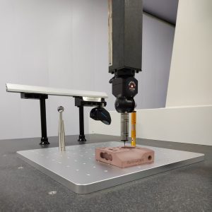
3D vision dimensional metrology systems deliver precision that meets the strictest manufacturing standards:
General Accuracy: Follows VDI 2630 guidelines, with typical accuracies of 4+L/100µm (L = measurement length in mm).
High-Precision Systems: Volumetric accuracy of 0.015–0.025 mm/m; average deviations as low as 0.005–0.008 mm/m (e.g., Mech-Eye UHP-140-GL camera with ±0.2 mm accuracy when paired with GD&T algorithms).
Micro-Measurement Capabilities: Coordinate measuring machines (CMM-integrated 3D vision) offer X/Y/Z-axis resolution of 0.5 μm—ideal for microelectronics (e.g., 0.2 mm solder joints) and medical devices (e.g., orthopedic implants).
Accuracy is ensured by:
Advanced Optical Design: Double-telecentric lenses minimize distortion; blue LED illumination reduces ambient light interference.
Calibration Protocols: Regular validation against NIST-traceable standards (e.g., ISO 10360-13); automated calibration reduces human error by 90%.
Environmental Control: Temperature stability (±0.5°C) and humidity control (35–85% non-condensing) prevent measurement drift—critical for aerospace components (e.g., turbine blades with ±10 μm tolerance).
2.2 Speed & Throughput: Ideal for High-Volume Production
Speed is a defining advantage of 3D vision metrology, addressing bottlenecks in mass manufacturing:
Scan Speed: High-speed systems capture 120 frames/second (640×480 resolution); higher frame rate cameras (300+ FPS) enable 3x faster operation for electronics assembly lines.
Throughput: Process tens of parts per second (e.g., 300 medical gears/hour vs. 10/hour manually); handle large parts (e.g., automotive doors) with 10-second synchronous scans.
Real-Time Feedback: In-line systems generate CAD-to-point-cloud deviation heatmaps and trigger MES alerts within 5 minutes—avoids batch defects (e.g., stamping errors in automotive panels).
A Tier-1 automotive supplier reduced scrap by 80% after implementing 3D vision: instead of offline CMM sampling (every 2 hours), 10-second scans detected edge gaps in real time, preventing defective batches from reaching downstream assembly.
2.3 Non-Contact Measurement: Protect Delicate & High-Value Parts

Non-contact 3D measurement eliminates the risks of contact tools, making it essential for fragile or high-value components:
Surface Damage Prevention: No probing = no scratches or deformation—critical for medical implants (e.g., titanium hip components) and electronics (e.g., transparent OLED screens).
Material Versatility: Specialized algorithms handle reflective metals (stainless steel pipe fittings), transparent plastics (injection-molded housings), and micro-featured surfaces (PCB solder masks)—one system replaces 3+ traditional tools.
Consistency: Avoids errors from probe wear (contact tools lose 5–10% accuracy annually) and surface contamination—measurement repeatability of 99.9% vs. 95% for CMMs.
In PCB manufacturing, 2D vision missed 8% of cold solder joints (due to no height data), while non-contact 3D scanners detected 99.4% of defects—saving $3.8 million/year in rework costs for Foxconn’s iPhone motherboard line.
2.4 Multi-Dimensional Measurement: Capture Complex Geometries
3D vision systems excel at X/Y/Z measurement, capturing features that 2D tools or contact methods miss:
Full-Dimensional Coverage: Measures flatness, perpendicularity, roundness, and internal features (e.g., porosity in die castings via industrial CT scanning) in one scan—eliminates cumulative errors from multi-step measurements.
Complex Feature Analysis: Line structured light scanning generates sectional profiles for automotive bumper beams; rotary laser scanning reconstructs thread profiles (taper, pitch, crest height) for pipe fittings.
Non-Destructive Testing: Industrial CT (paired with 3D vision) inspects internal structures (e.g., voids in molded parts) without disassembling components—reduces scrap by 40% in aerospace manufacturing.
For example, XTOM blue light 3D scanners detect 0.05 mm warpage in small injection-molded parts (e.g., earphone components), ensuring 100% compliance with design specs—something 2D vision or calipers can’t achieve.
3. Industrial Applications & Case Studies
3.1 Medical Device Manufacturing: Ultra-Precision Inspection
Medical devices demand sub-micron accuracy—3D vision dimensional metrology delivers:
Case Study: Medical Gear Inspection
Challenge: A manufacturer needed to inspect 10 mm-diameter gears (tooth thickness, pitch, groove depth) with ±5 μm tolerance. Manual tool microscopy yielded 10 parts/hour and 3% defects.
Solution: 360° structured-light 3D scanner.
Results:
Scanned full 3D models in 10 seconds (vs. 6 minutes manually).
Evaluated 20+ parameters automatically (vs. 5 manually).
100% inspection at 300 parts/hour; defect rate dropped to 0.1%.
Other medical applications:
Orthopedic implants: Verify 3D fit of hip cups (±10 μm tolerance) to reduce patient discomfort.
Surgical instruments: Inspect micro-serrations on scalpels (0.1 mm width) for cutting performance.
3.2 Automotive Industry: 100% In-Line Quality Control

Automotive manufacturing requires speed and safety—3D vision meets both needs:
Case Study: Automotive Body Panel Monitoring
Challenge: A Tier-1 supplier needed to detect edge gaps and dents in stamped doors/hoods. Offline CMM sampling (every 2 hours) risked batch defects.
Solution: Dual large-FOV 3D laser profilers at press exit.
Results:
10-second synchronous scans of entire panels.
CAD-to-point-cloud heatmaps triggered MES alerts within 5 minutes.
80% scrap reduction; predictive mold maintenance (detected wear before failure).
Other automotive use cases:
Bumper beam inspection: Measure 3D dimensions of plastic bumpers (±50 μm tolerance) for crash safety.
Casting quality control: Shanghai Meridian Magnesium (Ford/BMW supplier) used Creaform’s MetraSCAN 3D to reduce measurement time by 70% vs. CMMs.
3.3 Electronics & PCB Assembly: Micro-Solder Joint Inspection
Miniaturization (solder joints down to 0.2 mm) makes 3D vision essential for electronics:
Case Study: AI-Powered PCB Solder Joint Inspection
Challenge: Manual inspection (20x magnification) missed 8% of defects (e.g., cold joints, tombstoning); rework cost $1.2/board.
Solution: AI-driven 3D profilometry system (line laser, 500,000 points/second).
Results:
±2 μm accuracy; detected QFN lead height deviations of 0.05 mm.
99.4% defect detection for 0.3 mm pitch BGA solder balls.
Inspection time reduced from 120s to 22s/board; $3.8M/year in rework savings (Foxconn iPhone line).
AI enhances capabilities further: Algorithms analyze 20 million defect samples to identify cold joints (surface roughness >40%) and oxidation (ΔE >5)—mimicking human expertise but with 24/7 consistency.
3.4 Injection Molding: Warpage & Defect Detection
Injection-molded parts (e.g., appliance housings, automotive plastics) often suffer from warpage—3D vision solves this:
Case Study: Injection-Molded Housing Inspection
Challenge: An automation integrator needed to check 200×150 mm housings for ±50 μm hole positional accuracy. CMMs took 3 minutes/part.
Solution: Robot-guided laser line-scan 3D system (Zebra AltiZ sensors).
Results:
2-second scans; real-time warpage feedback to injection machines.
Cycle time down to 5 seconds/part; 25% yield increase.
Closed-loop control (adjusted mold temperature to reduce warpage by 30%).
Small parts (e.g., earphone components) benefit too: XTOM blue light scanners detect 0.01 mm deviations in miniature gears—ensuring proper fit in final products.
3.5 Precision Machining: Thread & Fastener Measurement
Stainless steel pipe fittings and fasteners require precise thread geometry—3D vision delivers quantitative data:
Case Study: Pipe Fitting Thread Inspection
Challenge: A manufacturer used go/no-go gauges (pass/fail only) for threads; 70% consistency, 60% customer complaints.
Solution: Rotary-stage laser spiral scanning system.
Results:
Reconstructed full thread profiles; measured pitch, crest height, taper.
Consistency improved to 99%; customer complaints down by 60%.
Detailed deviation reports enabled machining process optimization.
Advanced thread analysis algorithms evaluate pitch diameter, functional diameter, and lobular shapes—critical for oil/gas fittings (high-pressure applications).
4. Implementation Strategy: Get the Most Out of 3D Vision Metrology
4.1 Define Requirements & Select the Right System
Successful implementation starts with clear requirements:
Part Characteristics:
Size: Micro-components (<10 mm, e.g., PCB parts) vs. large assemblies (>1 m, e.g., truck frames).
Features: Planar (PCBs) vs. curved (turbine blades) vs. threaded (fasteners).
Accuracy Needs:
Follow the 10:1 rule: System precision should be 10x tighter than part tolerance (e.g., ±0.5 μm system for ±5 μm medical parts).
Throughput Goals:
High-volume (100+ parts/min): Choose ToF or laser triangulation systems (e.g., Mech-Mind Inline Measurement Solution).
Low-volume/high-precision: Opt for structured light scanners (e.g., Creaform MetraSCAN 3D).
Environmental Factors:
Dusty/wet environments: IP65-rated optics (e.g., Keyence IM-7000 series).
Vibration-prone areas (stamping shops): Vibration-damped mounts (reduces measurement error by 50%).
Example: A medical device manufacturer prioritized a structured light system (±1 μm accuracy) over a faster ToF scanner, while an automotive supplier chose a high-throughput laser profiler (tens of parts/second).
4.2 Environmental Integration & Setup
Industrial environments pose challenges—address these to ensure reliability:
Temperature & Humidity:
Operate within 10–35°C (optimal); use systems with -50–85°C range for extreme conditions (e.g., aerospace testing).
Keep humidity <80% non-condensing to avoid lens fogging.
Contamination Protection:
IP65/IP67 enclosures for optics in machining shops (protect against coolant, oil).
Air purging systems for dusty environments (e.g., foundries).
Line Integration:
Sync with conveyors/robots for pacing (e.g., robot-guided scanners for large parts).
Ensure MES/ERP compatibility (e.g., SAP, Oracle) for real-time data sharing.
Pro Tip: Conduct a site survey before installation to map vibration sources, temperature fluctuations, and space constraints—avoids costly rework later.
4.3 Data Management & Traceability

3D vision generates massive datasets—manage them to drive action:
Centralized Data Systems:
Use cloud-based platforms (e.g., Hexagon MMS) or on-premise solutions to store 3D models, reports, and defect images.
Reduce search time: Quality operators spend 3 hours/week managing files—effective systems cut this to 15–30 seconds via keyword/metadata search.
Metadata Strategy:
Tag data with context: Part number, production line, operator ID, device ID, timestamp.
Enables root-cause analysis (e.g., linking defects to a specific machine shift).
PLM Integration:
Hyperlink 3D data to Product Lifecycle Management (PLM) systems (e.g., Siemens Teamcenter).
Single-click access to measurements from PLM—accelerates design iterations by 30%.
Example: A PCB manufacturer used metadata to trace a batch of defective solder joints to a specific reflow oven—fixed the temperature setting and reduced defects by 75%.
4.4 Calculate ROI: Measure Business Impact
3D vision dimensional metrology delivers strong ROI across industries—here’s how to quantify it:
ROI Category Metrics Example Results
Labor Savings Manual inspection hours reduced; 100% labor replacement A medical device firm cut inspection labor by 80% (300 parts/hour vs. 10 manually).
Quality Costs Scrap reduction; rework savings; warranty cost decrease Automotive supplier: 80% scrap reduction; electronics firm: $3.8M/year rework savings.
Productivity OEE (Overall Equipment Effectiveness) improvement Average 22.7% OEE increase (faster inspection = less line downtime).
Time-to-Market Faster design validation; reduced setup time Aerospace component firm: Cut design iteration time by 40% via 3D scan data.
High-end systems deliver ~15% ROI in 5 years; mid-range systems ~12%—with some applications (e.g., PCB inspection) achieving payback in <8 months.
5. Future Trends in 3D Vision Dimensional Metrology
5.1 AI & Machine Learning: Smarter, Faster Inspection
AI is transforming 3D vision metrology, enabling autonomous quality control:
Defect Classification: Convolutional neural networks (CNNs) analyze 20+ million defect samples to build “digital pathology libraries”—detect cold solder joints, dents, and warpage with 99.4% accuracy (vs. 92% for traditional software).
Predictive Analytics: AI forecasts quality issues (e.g., mold wear, tool degradation) by analyzing historical 3D data—reduces unplanned downtime by 30%.
Auto-Programming: Systems like Koh Young KAP reduce setup time by 70% via AI-recommended inspection parameters—no expert programming needed.
Multi-modal data fusion (combining 3D point clouds, 2D images, and infrared thermal data) achieves I-AUROC scores of 0.952—40% lower false detection rates than single-modal systems.
5.2 Industry 4.0 & Digital Twins: Virtual Quality Control
3D vision is a cornerstone of Industry 4.0, enabling digital twin integration:
Virtual Testing: Digital twins of parts/components allow “what-if” testing (e.g., “How does warpage affect fit?”) without physical prototypes—cuts development costs by 25%.
Real-Time Sync: 3D scan data streams to digital twins (e.g., Siemens Process Simulate) for live quality monitoring—changeover times reduced by 70% via simulation.
Digital Thread: Track parts from design to service using 3D measurements—enables predictive maintenance (e.g., “Replace a gear when wear exceeds 10 μm”).
Example: A automotive OEM used digital twins to simulate body panel assembly—identified a gap issue via 3D scan data and fixed it before physical production, saving $2M in rework.
5.3 Advanced Imaging Technologies: Higher Resolution, Lower Cost
Emerging technologies are expanding 3D vision capabilities:
Blue LED Advancements: Higher-contrast patterns (10x better than white light) enable better measurement of reflective surfaces—cost reduced by 40% in the last 5 years.
Miniaturized Sensors: Compact 3D cameras (e.g., Orbbec Femto Mega) fit in tight spaces (e.g., robotic arms) while maintaining ±0.1 mm accuracy.
Nanometer-Level Systems: Interferometry-based 3D profilers (e.g., Bruker ContourGT) achieve sub-nanometer resolution—ideal for semiconductor wafers (10 nm features).
AI-enhanced imaging algorithms improve image quality (noise reduction, dynamic range) while reducing hardware costs—making high-precision 3D vision accessible to small/medium manufacturers.
5.4 Market Growth: Global Adoption on the Rise
The 3D vision dimensional metrology market is booming, driven by industrial demand:
Size: Projected to reach $5.8 billion by 2025 (19.3% CAGR, per industry reports).
Key Players: Hexagon AB (Sweden), Zeiss Group (Germany), Mitutoyo (Japan), Keyence (Japan), FARO (US)—offer end-to-end solutions (hardware, software, services).
Regional Growth:
Asia-Pacific: Fastest growth (electronics manufacturing in China, Vietnam).
Europe: Precision focus (automotive, aerospace in Germany, France).
North America: Advanced manufacturing (aerospace, medical in US, Canada).
Standardization (e.g., ISO 10360-13 for 3D vision CMS) is accelerating adoption—reducing evaluation complexity for manufacturers.
6. Standards & Compliance Framework
6.1 International Standards for 3D Vision Metrology
Compliance with global standards ensures accuracy, reliability, and interoperability:
ISO 10360-13:2024: Defines acceptance and re-verification tests for 3D vision coordinate measuring systems (CMS)—covers probing error, distortion, and spatial stitching accuracy.
VDI/VDE 2634: German standards for optical 3D measurement—Parts 2/3 address single-sided scanning and multi-viewpoint stitching.
ISO 13485: For medical device applications—requires 3D vision systems to have traceable calibration and audit trails.
China’s first national standard for optical 3D measurement (effective Sept 2025) adopts ISO 10360-13:2021 with localized adjustments—eases compliance for manufacturers in Asia.
6.2 Geometric Dimensioning & Tolerancing (GD&T)
GD&T is critical for communicating design intent—3D vision systems integrate GD&T capabilities:
Key Tolerances Measured: Flatness, parallelism, coaxiality, profile of a surface—all verified via 3D point clouds.
Automated GD&T Analysis: Advanced software (e.g., PolyWorks Inspector) extracts GD&T data from single scans—reduces manual calculation time by 90%.
Compliance: Meets ASME Y14.5 (US) and ISO GPS (global) standards—ensures parts are interchangeable across global supply chains.
Example: A turbine manufacturer used 3D vision to verify GD&T tolerances (coaxiality ±0.02 mm) on rotor shafts—ensuring smooth operation at 10,000 RPM.
6.3 Quality System Requirements
3D vision systems must align with quality management standards:
Calibration: Regular calibration against traceable standards (e.g., Kreon’s ISO 10360-08 certification)—ensures accuracy over time.
Validation: Qualify systems for specific applications (e.g., FDA QSR for medical devices); document performance with test parts.
Documentation: Maintain calibration certificates, operation manuals, and maintenance logs—supports audits (ISO 9001, IATF 16949).
Pro Tip: Use systems with built-in calibration reminders—avoids missed deadlines that risk non-compliance.
6.4 Regulatory Compliance by Industry
Regulations vary by sector—here’s what to consider:
Medical Devices: FDA QSR (US), EU MDR—requires 3D vision systems to have data integrity controls (audit trails, no data manipulation).
Automotive: IATF 16949, ISO/TS 16949—needs traceability from 3D measurements to final vehicles.
Aerospace: AS9100—demands high accuracy (±1 μm) and environmental stability (±0.5°C).
Electronics: RoHS, REACH—3D vision helps verify component compliance (e.g., lead-free solder joints).
Example: A medical device firm used 3D vision data to prove compliance with FDA QSR—reduced audit findings by 60% vs. manual records.
7. Conclusion: 3D Vision Metrology—The Future of Industrial Quality Control
3D vision dimensional metrology has evolved from a niche tool to the digital backbone of modern manufacturing. Its technical advantages—unmatched accuracy (sub-micron to mm/m), speed (tens of parts/second), non-contact operation, and multi-dimensional measurement—solve critical quality control challenges across industries.
Real-world case studies prove its impact: medical device firms achieve 30x faster inspection, automotive suppliers cut scrap by 80%, and electronics manufacturers save millions in rework. With AI integration, Industry 4.0 compatibility, and a booming global market ($5.8B by 2025), 3D vision is no longer optional—it’s a strategic imperative for competitiveness.
For manufacturers, the path forward is clear: Define your requirements, select the right system, integrate it into your workflow, and leverage data to drive continuous improvement. As manufacturing evolves toward intelligentization and zero-defect production, 3D vision metrology will remain central to achieving quality, efficiency, and innovation.
The digital cornerstone is laid—now it’s time to build with 3D vision