











Published by MEAXPERT | Cost-Effective Precision Measurement Solutions
Introduction: Why Wire Bonding Inspection Matters in Optical Communication
Optical communication devices are evolving rapidly toward higher transmission rates, higher levels of integration, and increasingly compact package designs. Modern high-speed optical modules and silicon photonics components adopt miniaturized structures and densely packed circuits, making dimensional accuracy and structural consistency increasingly important to manufacturing yield and long-term device reliability.
Wire bonding is a critical interconnect process in optical communication and semiconductor packaging. Ultra-fine gold wires establish electrical connections between optical chips, substrates, and other package components. Key geometric attributes—including wire loop height, arc profile, spatial positioning, and geometric consistency—directly influence packaging integrity, electrical performance, and long-term device stability.
As packaging technology advances, bonding patterns are becoming denser, with more fine wires integrated within increasingly compact packages. This trend creates stricter requirements for inspection stability and repeatability. Traditional manual inspection and conventional optical methods can struggle to balance fine-feature measurement, repeatability, and scalable batch throughput. As a non-contact measurement technology, vision measurement machines (VMMs) provide a practical solution for wire bonding inspection, particularly where dimensional accuracy, repeatability, and automated measurement are required.

- Key Measurement Challenges in Fine Wire Bonding
Wire bonding inspection appears straightforward in principle, yet the micro-scale, optically reflective, and densely packed nature of modern bonding layouts creates consistent measurement challenges. Conventional inspection workflows often fail to deliver stable, repeatable results for high-end optical communication packaging.
1.1 Ultra-Fine and Highly Reflective Wires Challenge Optical Imaging
Bonding gold wires used in optical chip packaging are extremely fine and feature smooth, highly reflective metal surfaces. Under conventional fixed lighting conditions, strong surface reflections can reduce image contrast and make it difficult to distinguish wire edges from surrounding chips, bonding pads, and substrate features. Complex stacked packaging structures may also cause partial occlusion, limiting the ability of standard vision systems to reliably identify wire contours and peak heights, potentially resulting in measurement variability.
1.2 Three-Dimensional Wire Loops Require Reliable Z-Axis Measurement
Bonding wires form continuous curved three-dimensional loops rather than flat planar features. Loop height is a critical packaging parameter that directly affects the clearance between the wire loop and surrounding package structures. Conventional 2D vision inspection primarily captures planar image information and therefore cannot directly provide reliable Z-axis information for a three-dimensional wire loop. Without calibrated depth referencing, it can be difficult to consistently determine the true peak height relative to the package datum.
1.3 Dense Bonding Patterns Create a Magnification–Field-of-View Trade-Off
Modern high-density optical packages can contain dense arrays of bonding wires within a very limited footprint. Conventional optical inspection often involves a trade-off between magnification and field of view. Lower magnification provides a larger field of view but may reduce the ability to resolve fine wire features, while higher magnification improves feature visibility at the expense of field of view. Operators are forced to reposition and reframe repeatedly, resulting in slow, disjointed, and low-throughput inspection workflows.
1.4 Manual Positioning Limits Inspection Efficiency
Traditional wire bonding inspection relies heavily on manual feature positioning, point programming, and frame-by-frame measurement. For dense wire arrays, manual intervention increases inspection time significantly and introduces operator-dependent variability. The lack of standardized programmable workflows makes consistent batch inspection difficult to scale for high-volume production environments.
- How Is Gold Wire Height Measured? A Vision Measurement Approach
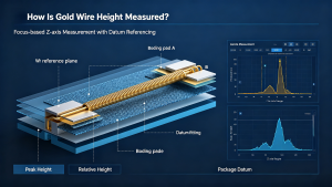
Gold wire loop height is one of the key inspection parameters in wire bonding. It can be used to evaluate the clearance between the wire loop and surrounding package structures and to identify excessive loop height or process variation. Unlike standard planar dimensional checks, wire height inspection requires reliable depth acquisition and stable datum referencing to deliver consistent, production-ready results.
Professional vision measurement workflows address this challenge through calibrated optical imaging and focus-based Z-axis measurement. The system acquires focused images at different Z positions across the wire loop profile, allowing depth variations to be resolved beyond a single image plane and helping identify the wire’s highest point more reliably. By sampling multiple focal planes, the system can resolve depth variations that are not available from a single image plane, helping identify the wire’s highest point more reliably.
To ensure meaningful dimensional data, the measurement routine incorporates reference plane fitting based on stable chip and substrate features. Relative height is calculated between the detected wire peak and the fitted package datum. This method reduces measurement variability caused by component tilt or minor positional offset, providing repeatable wire height measurements for curved wire geometries.
- How Vision Measurement Machines Support Wire Bonding Inspection
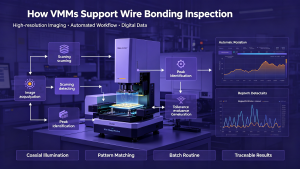
Modern VMMs integrate calibrated optical hardware, adjustable illumination, precision motion control, and specialized measurement software to address core wire bonding inspection challenges. The combination delivers repeatable, programmable, and data-enabled quality control for optical communication packaging.
3.1 High-Resolution Optical Imaging
VMM platforms support flexible magnification adjustment to resolve ultra-fine bonding wire features. Configurable multi-segment illumination combines coaxial and incident lighting to reduce reflective glare and improve edge definition across metallic wires, bonding pads, and substrate surfaces. Optimized imaging conditions help maintain stable feature recognition despite minor variations in surface reflectivity or package structure.
3.2 Focus-Based Z-Axis Measurement for Wire Height Inspection
Depending on the system architecture, VMMs can use focus-based depth measurement techniques to evaluate the three-dimensional geometry of wire loops. By capturing and correlating focused images across a defined Z-axis range, the system can characterize depth variations along the wire loop and identify its peak height. Paired with datum plane fitting, this approach delivers standardized height measurement that supports consistent process monitoring.
3.3 Automated Positioning and Batch Measurement
Using pattern matching and feature recognition functions, VMMs establish repeatable measurement coordinates and automate workpiece alignment. Once inspection recipes are configured, the system can automatically execute positioning, imaging, measurement, and tolerance evaluation across predefined bonding wire locations. Programmable batch routines reduce repetitive manual programming and operator-dependent variability, improving overall inspection throughput and consistency.
3.4 Digital Measurement Data for Quality Control
All inspection results are automatically logged, evaluated against defined tolerances, and compiled into standardized reports. Traceable measurement data supports batch comparison, process trend analysis, and root-cause troubleshooting. Digitized inspection records enable manufacturers to stabilize bonding processes and implement continuous packaging quality improvements.
- Key Inspection Parameters for Optical Communication Wire Bonding
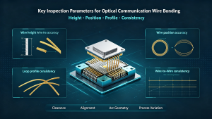
Effective wire bonding quality control relies on multi-dimensional geometric verification, rather than height measurement alone. Core inspected parameters support packaging reliability and process stability validation.
- Wire Height: The vertical distance from the wire’s peak loop to the package reference plane, used to verify internal clearance and prevent structural interference during assembly and operation.
- Wire Position Accuracy: Evaluates wire alignment relative to bonding pads and chip fiducials to ensure stable electrical interconnection and consistent packaging alignment.
- Loop Profile Consistency: Inspects the uniformity and smoothness of wire arc geometry to identify abnormal bending, sagging, or distortion that may compromise long-term structural reliability.
- Wire-to-Wire Consistency:Evaluates dimensional and positional consistency across multiple bonding wires on the same device or within a production lot, helping identify process variation and changes in bonding parameters.
- Vision Measurement vs. Manual Inspection for Production Quality Control
Manual inspection can be useful for R&D verification, troubleshooting, sampling inspection, and low-volume applications. However, as inspection volumes and measurement points increase, manual methods become more difficult to standardize and scale. Vision measurement systems provide a repeatable, programmable alternative optimized for production-grade quality control.
| Inspection Factor | Manual Inspection | Vision Measurement Machine |
| Measurement Method | Operator-dependent observation and manual calibration | Programmed, standardized measurement routines |
| Micro Feature Inspection | Limited by operator skill and optical setup, prone to variability | High-resolution imaging for stable fine-feature detection |
| Wire Height Measurement | Difficult to standardize, inconsistent results | Focus-based Z-axis measurement with datum referencing |
| Batch Inspection Efficiency | Labor-intensive and difficult to scale for high-volume production | Supports programmable batch inspection and scalable throughput |
| Result Consistency | Subject to operator-dependent variability | Improved measurement consistency across batches |
| Data Management | Manual logging and limited traceability | Automated logging and traceable digital records |
- How to Choose a Vision Measurement Machine for Wire Bonding Inspection
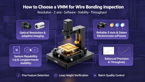
Selecting a suitable VMM for optical communication and semiconductor wire bonding requires evaluation of system-level performance rather than isolated specifications. The following criteria support reliable, production-ready inspection for fine bonding structures.
6.1 Sufficient Optical Resolution and Adaptive Imaging
The system should provide sufficient optical resolution to resolve ultra-fine wires, micro bonding pads, and relevant substrate features. Flexible, adjustable illumination is essential for stabilizing imaging on highly reflective metallic surfaces and complex packaged geometries, ensuring consistent feature detection across production batches.
6.2 Reliable Z-Axis and Datum Referencing Capability
For applications where wire height is a critical parameter, the system should provide reliable Z-axis measurement and an appropriate method for establishing the reference plane. Depending on the measurement architecture, this may include focus-based Z-axis measurement or other optical 3D measurement techniques to support accurate loop height verification.
6.3 Programmable Measurement Software
Production-grade inspection depends on robust software functionality. Key capabilities include automated pattern alignment, reusable measurement recipes, batch tolerance evaluation, and standardized report generation. These features reduce manual intervention and enable consistent, repeatable inspection workflows.
6.4 System Repeatability and Long-Term Stability
The selected VMM should maintain stable measurement performance over extended production cycles, minimizing measurement drift and supporting reliable long-term quality monitoring.
6.5 Balanced Precision and Throughput
A suitable solution should combine high-fidelity micro-feature measurement with practical batch throughput, supporting the inspection requirements of high-volume optical device manufacturing.
- Vision Measurement in Next-Generation Optical Communication Manufacturing
As optical communication technologies continue to advance toward higher transmission speeds, greater integration, and more compact device architectures, wire bonding structures are expected to become increasingly fine and densely integrated. Packaging quality control will increasingly require standardized, data-driven inspection capable of capturing subtle process variations.
Vision measurement machines support this industry transition by enabling non-contact, high-resolution inspection of delicate micro-structures. Programmable VMM workflows help manufacturers move from sporadic manual checks to systematic batch quality validation, providing consistent dimensional data to refine bonding processes and improve packaging yield.
Conclusion
Fine wire bonding is a critical micro-scale process that underpins the electrical performance and mechanical reliability of modern optical communication packages. Miniaturized, high-density bonding layouts create persistent inspection challenges for traditional manual and conventional optical methods, especially in wire loop height measurement and batch inspection repeatability.
Well-configured vision measurement machines address these challenges by combining high-resolution optical inspection, reliable Z-axis measurement, automated positioning, and traceable measurement data. For optical and semiconductor manufacturers, this provides a scalable approach to standardizing wire bonding inspection, improving production consistency, and identifying process variation at an earlier stage.
MEAXPERT provides cost-effective precision measurement solutions for manufacturers seeking practical CMM and vision measurement technologies for demanding industrial applications.