











Published by MEAXPERT | Cost-Effective Precision Measurement Solutions
Introduction: Precision Measurement for Miniaturized Optical Communication Components
As optical communication technology continues to advance, optical transceivers, photonic devices, and other high-density communication components are becoming increasingly compact and integrated. This trend raises stringent requirements for dimensional accuracy and manufacturing consistency of internal microstructures.
These microelectrode structures may incorporate fine conductive traces arranged in zigzag patterns, creating complex geometric features within a limited area.
Even minor deviations in line width, line spacing or gap dimensions can compromise device performance and reliability. For manufacturers, the challenge extends beyond capturing high-resolution images. It also involves inspecting large numbers of microscopic features efficiently and consistently in a production environment.
Vision Measuring Machines (VMMs) deliver a practical non-contact dimensional measurement approach for these fine geometric features. With optimized optical configurations, robust image processing and automated measurement routines, vision measurement helps manufacturers streamline microelectrode inspection and stabilize quality control.
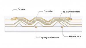
- Key Measurement Challenges in Optical Communication Microelectrodes
Zigzag microelectrodes combine ultra-fine traces, intricate geometric layouts and large volumes of measurement locations. Their key inspection challenges fall into three main categories:
1.1 Fine Feature Recognition
Microelectrode traces are significantly smaller than conventional machined features. Measuring their line width, spacing and narrow gaps requires sufficient image resolution and reliable edge recognition.
Reflective metallic thin-film surfaces can create imaging challenges. Surface glare, uneven illumination and inconsistent contrast may obscure true feature boundaries against the background.
A capable measurement system must provide:
- Sufficient optical magnification and resolution for fine geometric features
- Tunable illumination to boost edge contrast
- Stable image capture and edge detection
- Repeatable readings for line width, spacing and gap dimensions
The optical setup must be selected based on material, surface finish, feature size and defined tolerances.
1.2 Complex Geometric Patterns
Unlike isolated holes or simple rectangular features, zigzag microelectrodes contain interconnected line segments, sharp corners and narrow gaps. Numerous features are tightly packed within a single field of view, generating dozens or hundreds of measurement points per workpiece.
Traditional manual inspection requires operators to locate and select each feature one by one. Repeated positioning and point selection extend cycle time and introduce operator-dependent variability. Robust inspection workflows therefore require automated feature recognition, unified coordinate referencing and batch measurement support.
1.3 High-Density Measurement
Microelectrode inspection runs through multiple manufacturing stages: incoming substrate verification, in-process QC and final product validation. As production volumes rise, the total number of measurement points multiplies rapidly.
When every point requires manual triggering, inspection quickly becomes a production bottleneck. Manufacturers need measurement solutions that balance accuracy, coverage and throughput while cutting repetitive manual work.
- How Vision Measuring Machines Improve Microelectrode Inspection

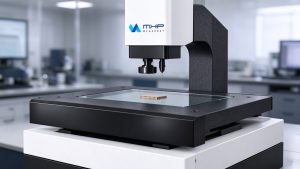
Vision Measuring Machines use optical imaging and image processing to capture visible geometric features without physical contact with the workpiece. For microelectrode inspection, a properly configured VMM quantifies two-dimensional geometric characteristics including:
- Line width:Width of individual conductive traces
- Line spacing:Distance between adjacent electrode traces
- Gap dimensions:Narrow clearances between neighboring features
- Pitch and pattern spacing:Regularity of repeated structures
- Geometric positioning:Relative alignment of selected features
Automated vision measurement reduces repetitive positioning and manual input. Four technical pillars are critical for this application:
2.1 High-Magnification Optical Imaging
A matched optical system is fundamental to resolving fine electrode boundaries and capturing the geometric details required for dimensional evaluation.
For zigzag microelectrode structures, accurate line-width measurement depends on the system’s ability to identify both straight edges and boundary transitions around corners. Stable edge detection is therefore essential for obtaining consistent dimensional results across different sections of the same conductive trace.
Depending on workpiece size and tolerances, manufacturers select appropriate magnification, camera hardware and optical resolution for their application.
It is important to note that magnification alone does not guarantee accuracy. Optical resolution, image quality, system calibration, edge-detection stability and operating conditions all play decisive roles.
2.2 Flexible Illumination for Metallic Thin-Film Surfaces
Lighting directly impacts image contrast and edge detection reliability.
For reflective metallic thin films, coaxial illumination can help improve image contrast by directing light along the optical axis. Contour illumination can enhance the visibility of feature boundaries, depending on the workpiece geometry and surface characteristics.
Where supported by equipment, combining different illumination modes allows engineers to tune imaging conditions for specific surface and edge characteristics. The goal is consistent, well-defined feature boundaries for repeatable dimensional measurement.
2.3 Automated Focus and Coordinate Referencing
Consistent positioning is critical when measuring dozens of features spread across a microelectrode pattern.
Suitable geometric reference features can be used to establish a workpiece coordinate system, providing a consistent reference for all measurement features and subsequent measurement cycles. Automated focusing helps maintain image sharpness when acquiring measurement data at different feature locations, subject to machine configuration.
These functions reduce reliance on repeated manual positioning and create a structured, reproducible measurement workflow.
2.4 Automatic Measurement Point Merging for High-Density Inspection
One of the key challenges in microelectrode inspection is the large number of measurement points distributed across dense geometric patterns. When each point requires individual selection and measurement, the inspection process can become time-consuming, particularly for workpieces containing hundreds or thousands of locations.
Automatic measurement point merging provides a more efficient approach by combining applicable measurement locations into a batch measurement operation. Instead of handling each point individually, operators can simplify the measurement workflow and reduce repetitive software operations.
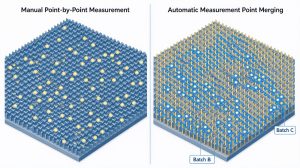
For microelectrode structures with numerous closely spaced features, this capability can significantly improve inspection efficiency while maintaining a consistent measurement procedure, provided that the measurement software supports the required feature recognition and point-merging functions.
- A Typical Vision Measurement Workflow for Microelectrodes
This streamlined procedure improves repeatability and simplifies result evaluation.

Step 1: Establish the Workpiece Coordinate System
Place the microelectrode substrate on the stage, identify suitable geometric reference features and establish the workpiece coordinate system as a stable reference for all subsequent measurements.
Step 2: Configure Imaging and Illumination
Select magnification and camera settings matching the trace dimensions. Adjust illumination to achieve clear contrast between metallic features and the substrate. For reflective surfaces, test coaxial and contour illumination to confirm the optimal imaging setup.
Step 3: Focus and Identify Measurement Features
Enable auto-focus where available. Target required geometric items: individual electrode line widths, inter-trace distances, local gaps at zigzag bends, pattern pitch and positional relationships. Reliable feature identification is the foundation of valid dimensional data.
Step 4: Apply Automated Measurement and Measurement Point Merging
Build measurement programs for target features. Where software permits, leverage automatic measurement point merging to group eligible locations within the same field of view. This cuts repetitive manual operations and simplifies inspection of densely packed features.
Step 5: Evaluate Results and Generate Reports
Compare measured dimensions against drawing tolerances. Export inspection reports with full dimensional data, enabling quality engineers to flag deviations and assess manufacturing consistency. Data can support process troubleshooting when recurring dimensional drift appears.
- Key Benefits of Automated Vision Measurement for Microelectrode Manufacturing
Automated optical imaging, programmed measurement routines and batch feature evaluation deliver tangible operational advantages for precision manufacturers.
4.1 Higher Inspection Efficiency
Automated measurement routines reduce repetitive operator intervention by processing multiple measurement locations within a predefined program. For microelectrode structures with hundreds or thousands of measurement points, this can substantially shorten inspection time and improve measurement throughput.
In the cited industry case, an optimized vision measurement setup demonstrated that a thousand-point measurement task could be completed within minutes instead of hours under a well-tuned program and configuration. Actual cycle time varies by workpiece geometry, measurement strategy, imaging conditions, software performance and total feature count. This represents a specific application benchmark, not a universal performance guarantee for all systems.
4.2 More Consistent Measurement Procedures
Manual inspection relies on operator judgment when identifying edges and selecting measurement positions. Automated programs standardize coordinate references, feature definitions and measurement procedures, reducing operator-dependent variation and improving consistency across inspection batches.
4.3 Faster Identification of Manufacturing Deviations
Consistent dimensional measurement provides reliable data on critical microelectrode parameters, including line width, line spacing and local gap dimensions. By comparing results across production batches, engineers spot dimensional trends and abnormal shifts early. This supports root-cause investigations into potential manufacturing issues, including dimensional inconsistencies and patterning variations.
4.4 Improved Support for Production Quality Control
Efficient multi-feature measurement makes automated vision inspection suitable for multiple stages of production quality control:
- Incoming patterned substrate inspection
- In-process dimensional verification
- Final microelectrode inspection
- Cross-batch comparative evaluation
- Process monitoring and trend analysis based on dimensional data
By cutting repetitive inspection work and unlocking reliable dimensional data, VMMs strengthen end-to-end quality control.
- How to Select a Vision Measuring Machine for Microelectrode Inspection
Choosing a suitable VMM requires deeper evaluation than just comparing nominal accuracy or magnification figures. Manufacturers should assess requirements specific to their microelectrode products.
5.1 Optical Resolution and Measurement Capability
The optical system must reliably resolve the smallest feature to be inspected.
Key evaluation criteria:
- Minimum electrode line width
- Minimum measurable gap
- Required dimensional tolerance
- Camera resolution and optical configuration
- Edge detection stability under real surface conditions
The required optical resolution should be evaluated against the smallest feature size and dimensional tolerance, rather than magnification alone. A higher magnification does not automatically guarantee better measurement accuracy.
A trial measurement with representative samples is strongly recommended to validate compliance with tolerance requirements.
5.2 Illumination Adaptability
Different metallic films, substrate materials and surface finishes demand tailored lighting schemes. The selected system must offer flexible illumination options to optimize contrast and feature recognition for your actual workpiece.
5.3 Software Automation and Measurement Efficiency
For microelectrodes with dense repeated geometric features, software functionality heavily shapes overall throughput. Prioritize these capabilities:
- Coordinate system construction
- Automatic focusing
- Geometric feature recognition
- Batch measurement
- Automatic measurement point merging
- Program saving and reuse
- Custom inspection report generation
Assess these functions against the feature complexity and quantity in your inspection task.
5.4 Repeatability and Measurement Validation
Measurement consistency is critical when dimensional data drives production monitoring. Validate repeatability with representative workpieces, fixed measurement programs and stable environmental conditions.
Calibration, metrological traceability, measurement uncertainty and tolerance evaluation should all be incorporated into a formal inspection process.
- MEAXPERT Vision Measurement Solutions for Microelectronic Applications
At MEAXPERT, we provide cost-effective vision measurement solutions designed to meet the dimensional inspection requirements of precision manufacturing.
For optical communication components and microelectronic applications, dimensional inspection often involves fine geometric features, closely spaced structures, and strict requirements for measurement consistency.
A suitable Vision Measuring Machine can help manufacturers inspect critical two-dimensional characteristics, including:
- Fine contours and microstructures
- Line widths and spacing between adjacent features
- Small gaps and geometric distances
- Hole diameters and positional relationships
- Repeated patterns and dimensional consistency
Choosing the right measurement solution requires evaluating the workpiece geometry, smallest feature dimensions, required tolerances, optical conditions, and inspection volume.
MEAXPERT focuses on practical measurement configurations that balance optical performance, measurement efficiency, and equipment investment, helping manufacturers establish reliable dimensional inspection processes for precision components.
Whether inspecting microelectronic patterns, precision connectors or other small components, MEAXPERT helps manufacturers identify suitable vision measurement configurations based on their specific dimensional requirements and production needs.
Conclusion: Making Microelectrode Inspection More Efficient with Optical Measurement
Zigzag microelectrodes present significant inspection challenges due to their fine conductive traces, dense geometric layouts and large numbers of measurement points.
Vision Measuring Machines provide a non-contact approach to inspecting these two-dimensional features. Combined with suitable optics, flexible illumination, coordinate referencing and automated measurement routines, they help streamline inspection workflows and improve measurement consistency.
For manufacturers, the value of vision measurement lies not only in capturing microscopic dimensions, but also in making dimensional inspection more efficient, repeatable and practical for production quality control.
Looking for a cost-effective vision measurement solution for microelectrodes or other precision components? Contact MEAXPERT to discuss your dimensional inspection requirements.
Frequently Asked Questions (FAQ)
- What is a Vision Measuring Machine used for in optical communication manufacturing?
A Vision Measuring Machine is used for non-contact dimensional inspection of visible geometric features in precision components. In optical communication manufacturing, it can help measure microelectrode line widths, spacing, gaps, contours, and other two-dimensional geometric characteristics, depending on the optical configuration and measurement method.
- What dimensions can be measured on zigzag microelectrodes?
Typical measurement characteristics include conductive trace width, spacing between adjacent lines, local gaps around bends, pattern pitch, and selected geometric relationships. The measurable features depend on image quality, optical resolution, workpiece surface conditions, and measurement software capabilities.
- Why is non-contact measurement important for microelectrodes?
Microelectrodes contain delicate metallic patterns and fine structures. Non-contact optical measurement avoids direct probing forces that could potentially affect sensitive features, making it a suitable inspection approach for many microelectronic components.
- How does automatic measurement point merging improve inspection efficiency?
Automatic measurement point merging allows multiple measurement locations within a field of view to be processed in a batch rather than requiring individual manual selection and execution. This can reduce repetitive operations, particularly when inspecting workpieces with large numbers of densely distributed features.
- How do you choose a vision measuring machine for microelectrode inspection?
Important considerations include optical resolution, measurement accuracy, illumination adaptability, edge-recognition performance, software automation, repeatability, and inspection throughput. Testing representative workpieces under actual measurement conditions is recommended before selecting a system.